
Triple Vapor Recovery Unit · Membrane Series
Air-cooling + condensation + membrane separation process with high automation, compact footprint, low operating cost, processing capacity of 10–12 m³/h, vapor emission concentration ≤10 g/m³, compliant with national environmental standards.
Membrane Separation Process · Mature Domestic Route
Under pressure-driven conditions, separation is achieved by leveraging the differential adsorption capacity on the polymer membrane surface and the permeation rate differences within the membrane of each gas component.
High return on investment, stable operation, well-arranged process layout, outstanding cost-effectiveness, minimal on-site engineering, low operating cost—within the affordable range for corporate environmental facility investments.
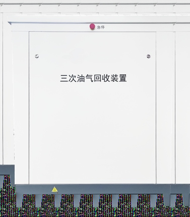
Main Unit
White explosion-proof cabinet integrating the control unit, actuators, heat-dissipation unit, signal acquisition, membrane modules, explosion-proof enclosure, and vapor piping. An emergency stop switch is mounted on the door panel.
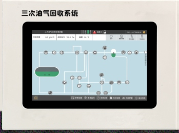
Control Console
10-inch color capacitive touchscreen running Android. Supports parameter configuration, real-time status display, record queries, fault alarms; real-time monitoring of underground storage tank pressure.
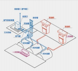
Gas Station Vapor Recovery Concept · Stage 1 / 2 / 3
To understand Stage 3 vapor recovery, one must start with the complete vapor recovery system. Stage 1 addresses vapors during unloading, Stage 2 addresses vapors during refueling, and Stage 3 addresses vapor emissions during storage.
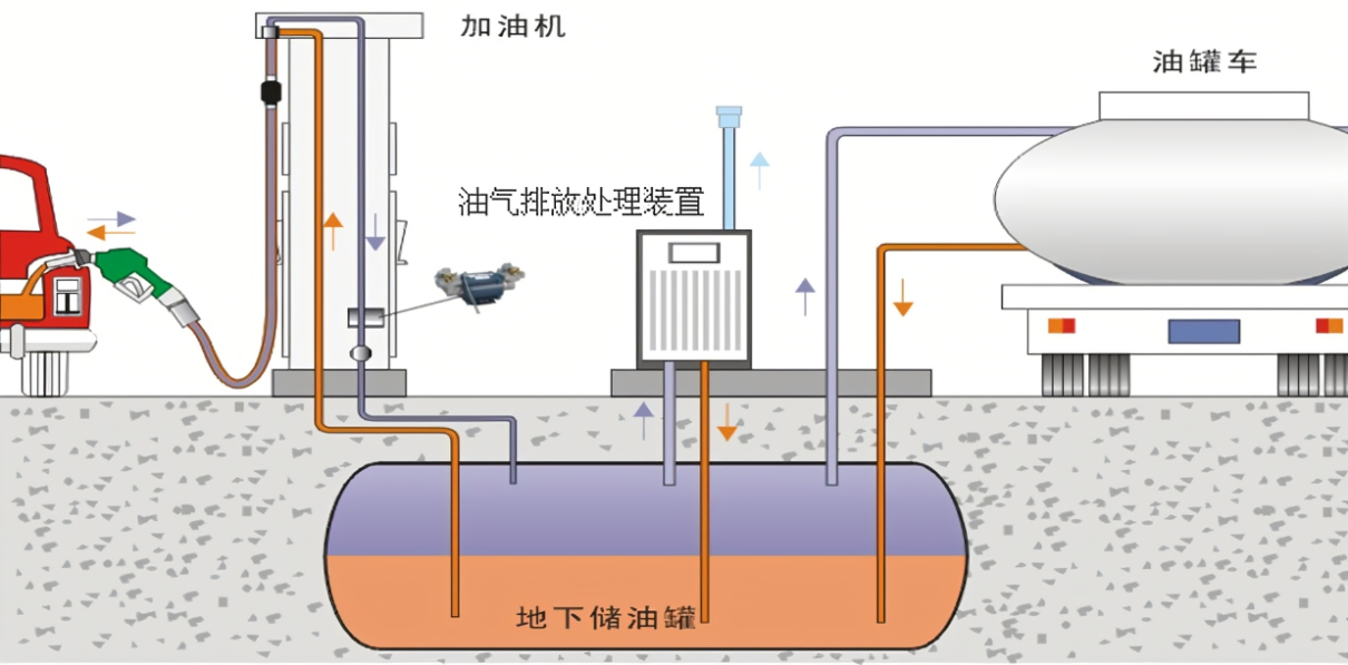
Stage 1: Unloading Vapor Recovery
When the tanker unloads gasoline, the vapors generated in the underground tank are collected in a sealed manner into the tanker's compartment, preventing vapor emissions during unloading.
Stage 2: Refueling Vapor Recovery
During refueling, the vapors displaced from the vehicle's fuel tank are recovered through the nozzle back into the underground storage tank, preventing vapor emissions during refueling.
Stage 3: Storage Vapor Recovery
Because the vapor volume from Stage 2 often exceeds the dispensed volume (vapor-liquid ratio >1), and combined with small breathing losses causing tank pressure rise, vapors would otherwise vent through the pressure-vacuum valve. Stage 3 recovery installs a treatment unit upstream of the pressure-vacuum valve to prevent pollution.
📌 Applicable Scenarios: Gas stations that have already completed Stage 1 / Stage 2 vapor recovery retrofit.
Equipment Principle · Air Cooling + Condensation + Membrane Separation
The Stage 3 vapor recovery system treats the vapors released from the storage tank. The system activates when the tank pressure reaches the set value (below the opening pressure of the pressure-vacuum valve).
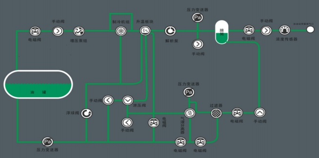
Process Flow
- 1. Air Cooling + Condensation: Vapor is compressed and condensed after entering the system; part is converted into liquid gasoline
- 2. Gas-Liquid Separation: Liquid gasoline is separated by the gas-liquid separator and returned to the tank
- 3. Membrane Separation: Uncondensed vapor enters the membrane module; clean air is separated and discharged to the atmosphere
- 4. High-Concentration Recirculation: High-concentration vapor returns to the tank, where part naturally liquefies
- 5. Auto Start/Stop: The system stops automatically when tank pressure falls below the set value or the run time ends
Liquefaction rate reaches 5‰, delivering excellent economic benefits
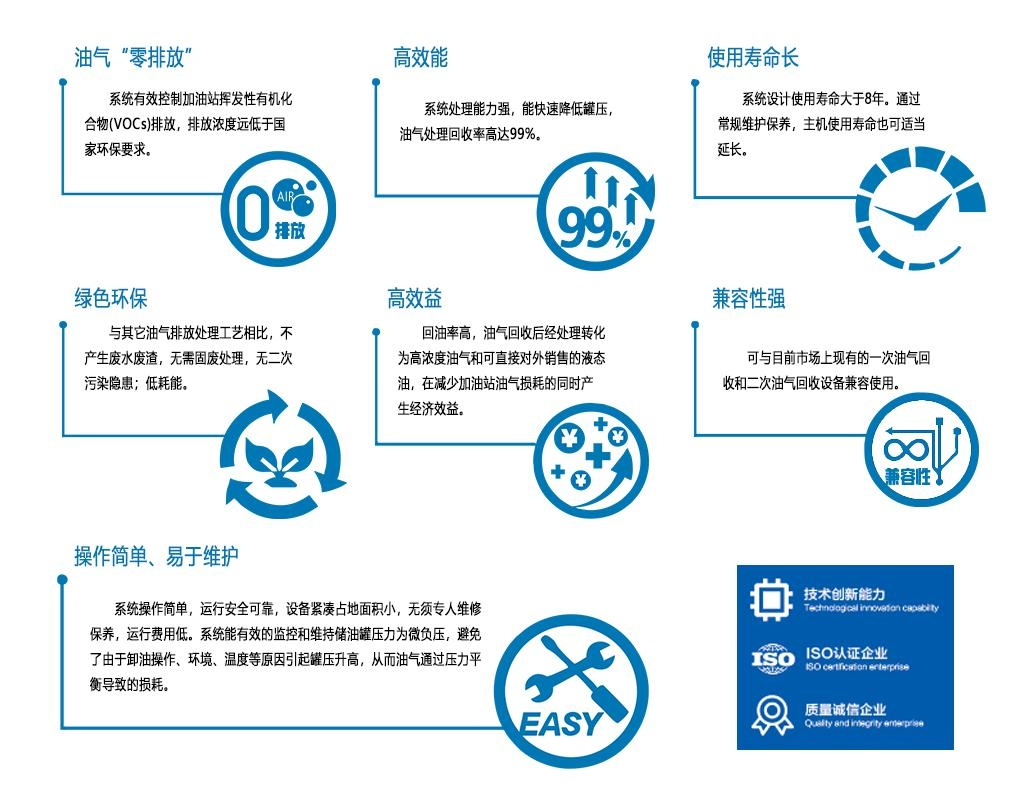
Seven Key Product Features
Automated monitoring & separation · Zero vapor emissions · High recovery rate · Compatible with existing vapor recovery systems
Technical Parameters
Industrial-grade configuration · Suitable for explosive gas environments Zone 1 / Zone 2 at fuel stations
Electrical & Explosion-Proof
- Explosion-Proof Mark
- Ex db eb ia [ia Ga] mb IIB T4 Gb
- Power Supply
- AC 380 V
- Total Power
- 2.9 kW
- Operating Ambient Temperature
- -50℃ ~ +60℃
Processing Capacity
- Processing Capacity
- 10 / 12 m³/h
- Processing Method
- Membrane Separation
- Start Pressure
- +150 Pa (adjustable)
- Stop Pressure
- -150 Pa (adjustable)
- Vapor Emission Concentration
- ≤ 10 g/m³
- Liquefaction Rate
- 5‰
Appearance & Configuration
- Dimensions (W × D × H)
- 1200 × 1100 × 1510 mm
- Configuration
- Compressor unit · Vapor separator · Filter · Refrigeration unit · Membrane module · Rotary vane pump · PLC control system · Concentration sensor
Smart Control
- Control Console
- 10-inch color capacitive touchscreen · Android OS
- HMI
- Parameters / Status / Records / Alarms / Tank Pressure Monitoring
- Network
- Network-enabled · Online upgrade
- Parameter Configuration
- Manual configuration of system parameters
Control System Interface
Android touchscreen · 6 main menus · Real-time monitoring of operating status
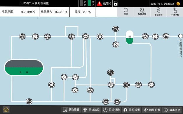
System Monitoring
Real-time equipment process diagram showing emission concentration / start pressure / temperature / emergency-stop status / alarm status / manual test / manual shutdown—full operating status at a glance.
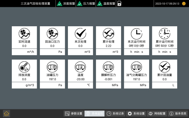
Monitoring Data
12 real-time metrics: live flow rate / return-port pressure / current run / cumulative processing / run time / emission concentration / tank pressure / temperature / membrane analysis pressure / vapor-separator tank pressure / cumulative oil return.
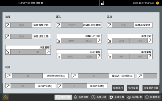
Parameter Settings
Three alarm thresholds for concentration / pressure / temperature, plus timing parameters (adsorption stop time / membrane pump delay / run duration) and calibration pressure—all system parameters manually configurable.
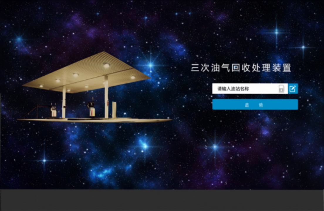
Startup Screen
Enter station name, one-tap equipment start; anti-misoperation design with emergency-stop button; time display + status indicator.
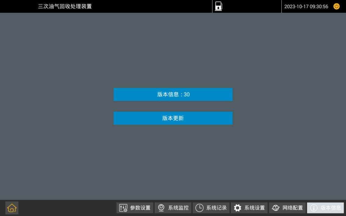
Version Information
System version display + online upgrade support; bottom 6 main menus for quick switch: Parameter Settings / System Monitoring / System Records / System Settings / Network Config / Version Info.
Equipment Installation Requirements
Main unit is suitable for installation in explosive gas environments Zone 1 and Zone 2 · Outdoor open-air · Well-ventilated
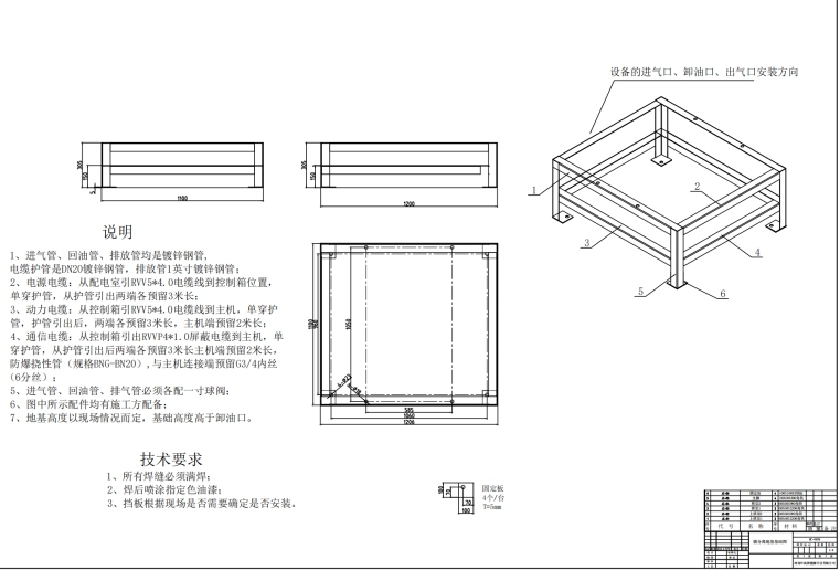
Foundation Drawing
Applicable to membrane-separation type; power cable GBRVV 5×2.5 + communication cable GBRVVP 4×1.0 shielded; grounding resistance R ≤ 4Ω; reserve 3 m of cable length.
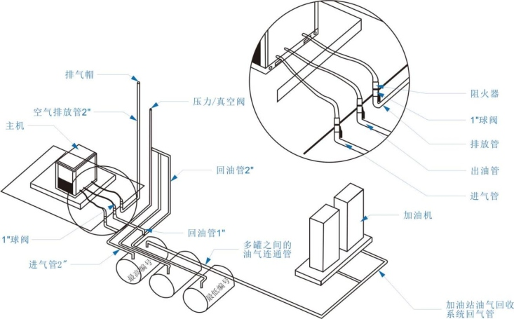
Site Installation Diagram
Main unit + storage tank + dispenser + flame arrestor + ball valve + exhaust / outlet / inlet piping + vapor equalizing line + exhaust cap (≥ 4 m).
9 Installation Specifications
- The main unit is suitable for installation in explosive gas environments Zone 1 and Zone 2
- The main unit should be installed outdoors in the open air at the fuel station, with good surrounding ventilation and on elevated ground to prevent water ingress
- The installation location should be in a quiet area at the station with minimal personnel traffic, but at least 3 meters from any wall or building
- The installation location should facilitate routing the inlet pipe from the tank's pressure-vacuum vent to the main unit and the return pipe from the main unit back to the tank
- A grounding device must be provided and connected to the existing grounding network, lightning & static electricity grounding resistance R ≤ 4Ω
- The inlet pipe should connect to the highest-octane gasoline tank's pressure-vacuum vent; the return pipe should connect to the lowest-octane gasoline tank
- Both the inlet pipe and return pipe should slope toward the tank, with a slope of no less than 1%; underground vapor piping must not use flexible hose
- The equipment exhaust pipe outlet should be at least 4 meters above ground level, with an exhaust cap installed at the outlet
- The main unit should be installed on a firm, level concrete surface, with the foundation raised 300 mm above ground to prevent water immersion; levelness ≤ 1.5 mm/m²
Need Vapor Recovery Retrofit?
Contact Zhiming Energy for triple vapor recovery unit selection and retrofit solutions.